Build Multilevel Process Configuration
Industrial 3D printing engineers were compensating for a broken mental model with spreadsheets. I led the end-to-end design of a feature that put the build structure back where it belonged: inside the software.
My Role
Senior Product DesignerProduct type
B2B Enterprise SoftwareYear
2022 - 2023Organisation
HP Inc. (3D Software Solutions)01 / Context
Industrial 3D printing is
not a simple workflow.
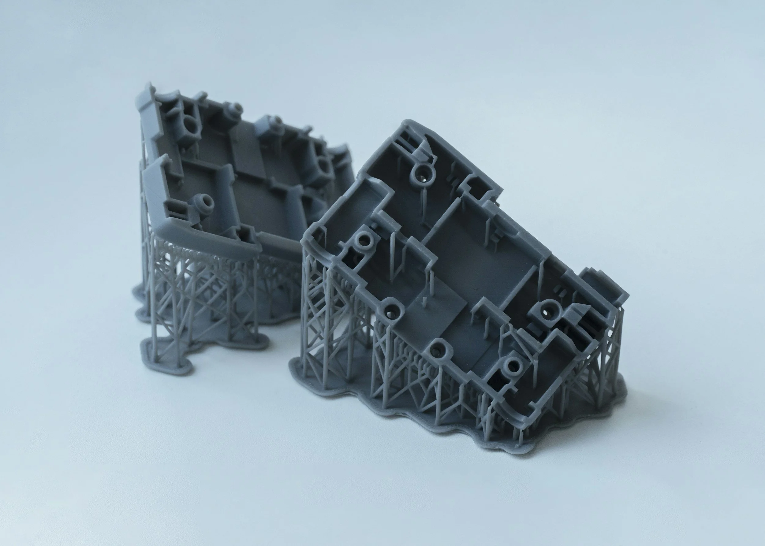
Before a manufacturer can reliably print a component at production volume, they need to run dozens of experiments. They adjust process parameters across multiple build levels, iterate until they hit a stable output, and then lock that configuration for scale. A single build is not flat. Level 1 might be a core material layer. Level 2 controls sintering agent concentration. Level 3 governs the surface finish pass. Each level has its own start point, usable height, stabilisation gap, and agent ratios.
The HP 3D Digital Production Suite is the software backbone of that process. When I joined the project at HP, the Process Development module let engineers create experiments and track build configurations, but it treated every build as a flat object. There was no way to define where one level ended and another began, no visual model of the build chamber, and no cross-level parameter comparison.
Engineers were compensating with spreadsheets. That's never a good sign.
The stakes were real. HP's industrial clients depend on repeatable, validated build configurations to scale to production. Every wasted print run is expensive. Every configuration error that slips through is a cost the engineer has to trace manually, often outside the software entirely.
02 / The real problem
The brief was a UI request.
The problem was trust.
The product team's stated ask was to add multilevel build parameters to the version side panel. I worked with the HP PM and application engineers to go deeper before touching any UI.
What I kept hearing in those sessions was not a feature request. When a build run produced bad output, engineers could not easily trace which level of the configuration was responsible. All the parameter data existed in the system, technically, but it was flat. Making sense of it required cross-referencing records, building the spatial picture mentally, and often exporting to a spreadsheet to do any meaningful comparison.
The real problem: the software had no model of the build structure. Engineers were constructing that model in their heads every time they opened a configuration. That overhead slowed iteration, introduced errors, and eroded confidence in the tool.
Reframed: engineers need to see the geometry of their build configuration, with each level's parameters anchored to its physical position in the chamber, before they can reason about it reliably. That shift changed the scope of what we designed. It was not about adding fields to a panel.
03 / Approach
End-to-end ownership,
cross-functional execution.
As a Senior Product Designer at HP 3D Software Solutions Org., I led the design process from discovery through to engineering handoff, working closely with the product manager, application engineers, and manufacturing partners at every stage.
Discovery came first. I ran sessions with HP application engineers to map their mental model: how they thought about level boundaries, how they reasoned about start points and usable heights, and what "checking a configuration" actually meant in their day-to-day workflow. Those sessions confirmed the spatial gap clearly. Engineers were conceptually comfortable with levels; they just had no way to work with them visually inside the tool.
I then worked on information architecture before any layouts. What data belonged at the build level versus the level level? What did engineers need to see immediately versus on demand? The level configuration accordion, the build visualisation, the cross-level parameter table, and the validation flow each emerged from that structural thinking, not from layout explorations.
Throughout the design phase I ran regular check-ins with the engineering team to validate that interaction patterns were implementable at the complexity we needed. The build visualisation required the most alignment: it was not in the original scope and needed a clear research-backed case to enter the brief.
04 / The work
Four surfaces,
one coherent system.
The design covers the full journey: configuring level boundaries, visualising the build structure spatially, editing per-level parameters, and catching configuration errors before they become failed print runs.
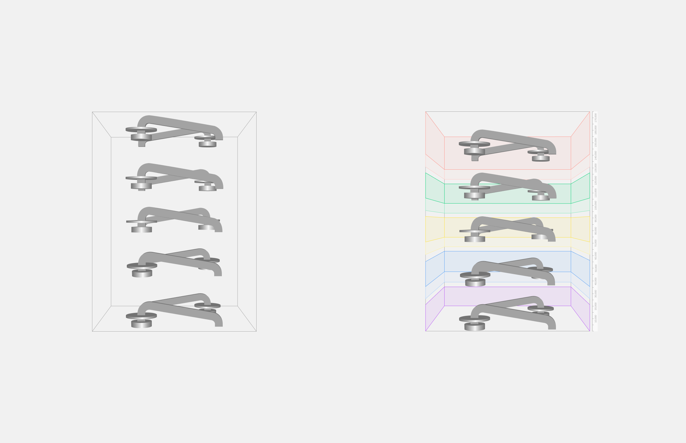
Screen 01 — Build visualisation: normal vs multilevel
The decision that changed the nature of the feature.
Left: a standard flat build. Five parts in a chamber, no spatial distinction between zones. Right: multilevel enabled. Each level is a distinct colour-coded band, with labels and height annotations on the right edge. The same five parts now sit clearly within their level boundaries. This visualisation was not in the original brief. I proposed it after discovery sessions confirmed engineers had no spatial reference for build structure inside the software. Getting it into scope meant building alignment across product, engineering, and HP stakeholders, grounded in what I heard in research. It is the single decision that transformed this from a parameter form into a configuration tool.
Screen 02 — Level configuration accordion
Defining the build structure.
The configuration panel lives in the Printing tab of Process Parameters. Engineers set platform height, build height, and level height adjustment globally, then configure each of the five levels individually: start point, usable height, and stabilisation gap. Levels are colour-coded consistently with the build visualisation, so the connection between spatial view and configuration panel is immediate. The "Validate parameters" action anchors to the bottom, after review, matching the mental model engineers already had from other precision software.
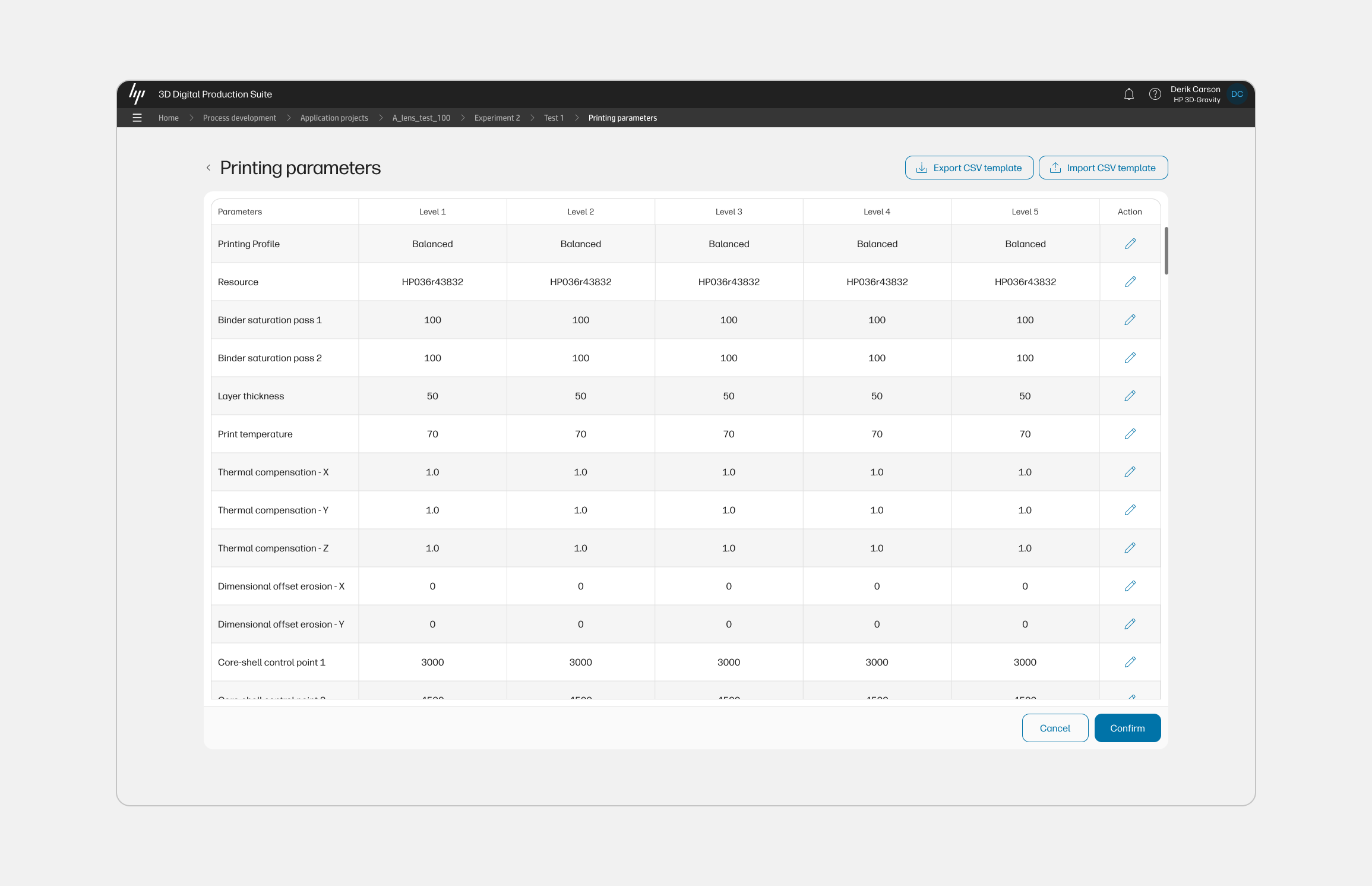
Screen 03 — Multi-level printing parameters
Comparing parameters across all five levels.
The full parameter matrix: printing profile, resource, binder saturation passes, layer thickness, print temperature, thermal compensation values, dimensional offset erosion, and core-shell control points, displayed per level in a single scrollable table. Rows are editable inline. Export and import CSV controls support batch workflows and cross-team collaboration. This is where the cross-level comparison that engineers were previously doing in spreadsheets becomes native to the tool. The table pattern emerged from a working session with the PM and engineering lead about what "comparison" actually meant in this workflow.
Screen 04 — Build visualisation error states
Validation that speaks the engineer's language.
Four variants showing how the system communicates level boundary violations. When a part extends beyond its configured level boundary, the build visualisation highlights the violation in red at the exact level where it occurs. Warning callouts name the level and its configured height, giving engineers the specific information they need to correct the configuration without leaving the screen. This error system was designed in close working sessions with HP's application engineers, who confirmed during validation that spatial specificity at the level of a boundary height was exactly what was missing from the existing workflow. An early version used a generic error list below the form. We replaced it with this.
05 / Key decisions
The calls that shaped
what shipped.
01. Consistent colour coding across every surface
The five build levels use the same colour system in the visualisation, the configuration accordion, the parameter table, and the error callouts. This required deliberate coordination across each part of the design. Without it, the visualisation would have been cosmetic. With it, engineers have one spatial reference system that follows them through every screen.
02. Errors in the spatial view, not in a list
The initial engineering approach to level validation was a list of errors below the configuration form. Working with HP's application engineers, I reframed it: the violation should appear where the violation exists, in the build chamber at the level where the part crosses the boundary. That specificity turned error messages from diagnostics into actions. Engineers knew exactly which level to correct without cross-referencing anything.
03. Parameter table for cross-level comparison
An earlier concept put level-specific parameters inside each accordion row. Through a working session with the PM and engineering lead, we identified the real workflow: engineers rarely configure one level in isolation. They compare across levels. A table with levels as columns and parameters as rows makes that comparison native, and it also unlocked the CSV export and import pattern the engineering team wanted for batch workflows.
04. Validate parameters as a deliberate final step
Validation was originally triggered automatically on change. Research sessions with engineers revealed that they expect to complete a full configuration pass before the system evaluates it. Moving validation to an explicit action at the bottom of the panel reduced noise, prevented premature errors mid-edit, and matched the mental model engineers brought from other precision tools they use daily.
06 / Business impact
The numbers behind
process development.
HP describes the 3D Process Development software as enabling customers to reduce time and costs associated with new process and application development and bring process knowledge in-house to create production-ready, customised settings. The ROI case is inseparable from the UX: a more legible process history means fewer wasted build runs, faster validated parameters, and more clients reaching production scale.
20%
Expected savings in total build costs with HP's Build Optimizer, validated by Forecast 3D as an early customer of the Digital Production Suite
Source: HP Formnext 2024 press release
21%
Improvement in printer utilisation through increased packing density and parts per build, attributed to capabilities in this software suite
Source: Forecast 3D / HP Formnext 2024
30%
Reduction in 3D print job setup time and operator errors, delivered through the features this work is part of across the production suite
Source: Internal project data
The business logic of better process configuration UX is direct. Industrial 3D printing is expensive per run. When engineers can identify which level of a build configuration failed, iterate faster, and reuse validated parameter sets, the cost-per-part drops. HP's strategy with the Digital Production Suite is built around this compounding effect: bring process knowledge in-house, run tighter experiments, scale production with confidence. The multilevel configuration design is part of that value chain.
Live product
HP 3D Digital Production Suite
The software this work shipped in, now commercially available for MJF and Metal Jet platforms.
07 / Reflection
Senior design is knowing
when to push.
The build visualisation was not in the brief. Getting it in required building a case across product, engineering, and HP stakeholders, grounded in what came out of discovery. That kind of contribution, recognising when a design decision changes the nature of a feature and then leading the conversation to make it happen, is what end-to-end ownership looks like in practice.
What made this project work was the collaboration. The error state design came out of working sessions with HP application engineers who described in precise terms what information they needed at the moment of a validation failure. The parameter table emerged from a conversation between me, the PM, and the engineering lead about what "comparison" actually meant in this workflow. The design is stronger because of those relationships, not despite the constraints they imposed.